When wanting to build a flexible control system using a CompactRIO from National Instruments, there has previously been a limitation on critical functions that requires safety classified hardware. About two years ago NI released the Functional Safety Module NI 9350, which fills this gap. In this blog post I will share my initial experience of using this module.
A while ago DVel delivered two control and measurement systems to Studsvik Nuclear AB. The systems are used to measure different properties of burnt fuel rods from the nuclear industry. The fuel rods are scanned over different measurement probes depending on which measurement is currently performed. The scanning system and probes are situated in a Hot cell, an area shielded off to the surrounding, where highly radioactive materials may be safely handled.
Protection of the equipment
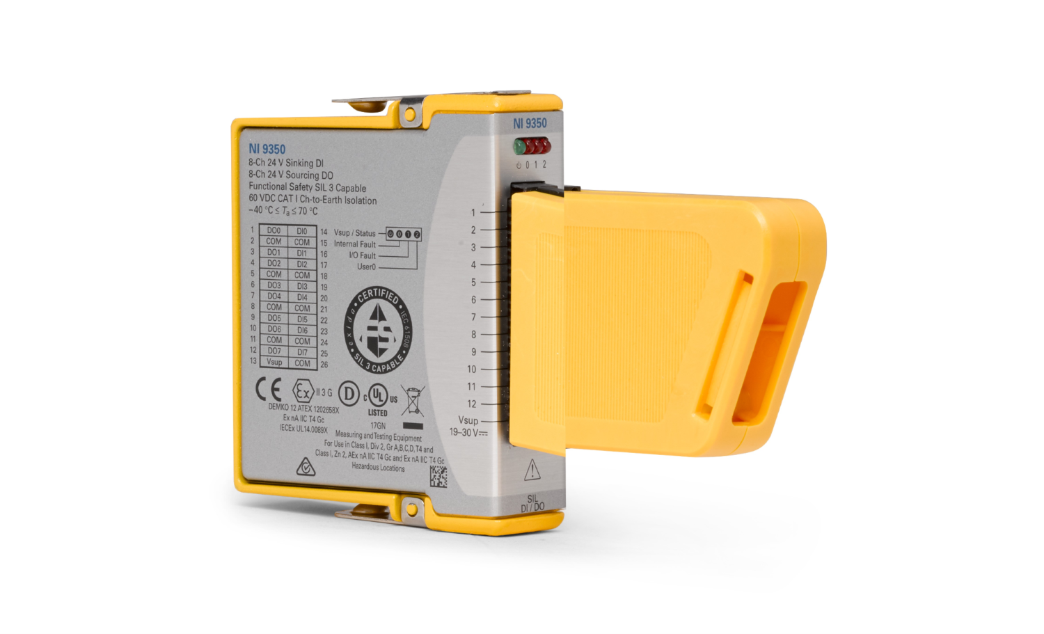
Due to the high level of radiation in the Hot cell, replacing damaged hardware becomes a timely and costly procedure. Therefore, the critical logic to protect the equipment, e.g. handling the switches limiting the scanning range, should be fool proof. The decision to use a CompactRIO real-time system was already made to solve the other requirements for the measurement system. Placing the critical damage control code as a separate part of the CompactRIO FPGA code was considered. However, to achieve an even higher level of assurance, we decided to use designated functional safety modules NI 9350 (see Figure 1).
SIL 3 classed safety module
The NI 9350 is a Digital In/Out Module certified to a Safety Integrity Level of class 3 (SIL 3). It is not classified to be used in a nuclear application, but it is a good choice in this case where the purpose is to secure the equipment.
Simple configuration
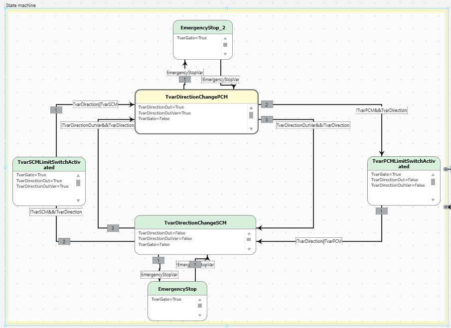
It contains an on-board FPGA, making each module a self-contained safety logic solver. The logic is programmed using the NI Functional Safety Editor and separately downloaded to each safety module. Figure 2 shows one of the state machines in one of the safety modules. The rectangles represent different states where variables (internal and output signals) are set according to the statements in each box. The arrows between the boxes represent state transitions, where the text on the arrows defines the condition for the transition.

State machine for monitoring limits switches on the horizontal axis. It prevents the horizontal stepper motor to move left if the left limit switch is triggered and to move right if the right limit switch is triggered.
In this project three stepper motors and eight limit switches were controlled and monitored using two NI 9350 modules. The NI 9350 was utilized to deactivate the stepper motor drivers and activate a magnet brake. As inputs, limiting switches on the axes, on the measurement probes and for a drive belt as well as status signals from the stepper motor drivers and emergency stops were used.
Signals visible from the CompactRIO system
The state machines in the module works independently from the rest of the code on the CompactRIO, since they run on the module itself. However, the status of the digital input/output on the module can be monitored from a LabVIEW application running on the CompactRIO. This can be done using Scan or Hybrid interface mode in the CompactRIO communication. Thus, the status of the limit switches could be read by the software without the need for an additional I/O module.
An attractive option in comparison to using a separate SIL classed PLC
Although it requires some effort to code in a new interface, the Functional Safety Editor is simple and easy to learn. It is also easy and quick to transfer the generated logic to the module. In comparison to using a separate SIL classed PLC, the NI 9350 and Functional Safety Editor is an attractive option.
By Linus Ros

Riki Virc
VD
